Last Updated on September 17, 2022
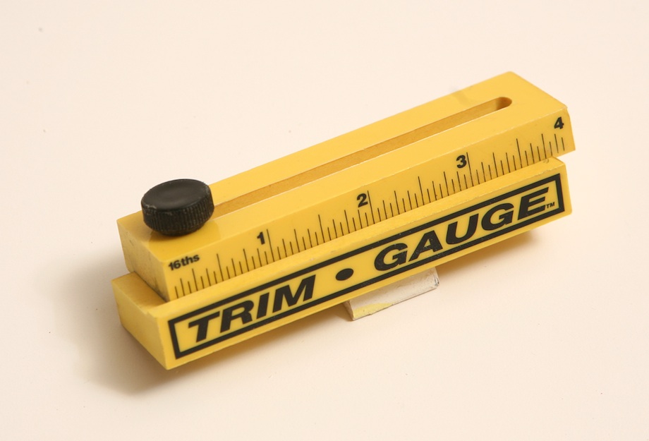
Before beginning the installation process, it is important to understand how the Trim Gauge(tm) is installed. Place it in an upper corner of a door jamb so the bottom of the gauge rests on the jamb, but the top protrudes over the jamb. With a pencil, draw a line along the gauge on the jamb below. Repeat the process for the other jamb. The line should intersect twice. Use the Gauge as a reference point when determining where the trim should be placed.
Repairing a trim gauge
If the pointer on your car’s trim gauge won’t move, try the following: disconnect the terminals. Then, test the voltage. If it reads higher than it should, the problem is most likely in the wiring of the gauge. Replace the gauge if necessary. It should read higher than it should when the ignition is on. Check the voltage by shorting the terminal to the ground. Afterward, reconnect the terminals.
In most cases, a trim sensor unit is a simple piece of kit. The mechanical functions of this part should be obvious. The arm should move up and down in relation to a bracket or tab. On a Yamaha engine, the plastic tab may break. If this happens, you should replace the trim sender unit with a metal one. In some cases, there are multiple terminals on the gauge. In some cases, they are wired into separate circuits.
While marine gauges are not particularly complex, they are still sensitive to marine conditions. While they can be difficult to repair, the gauge itself is not complex. In many cases, the problem is the sender or wiring. Repairing a trim gauge is an easy task, as long as you follow these tips. Remember to pay attention, however, and don’t ignore warning signs of impending danger! And remember to pay attention – the most important skill of all when boating.
First, you must adjust the trim sender. This should be done manually with the car in the down position. Afterwards, you need to reattach the trim sender and make any final adjustments. Finally, you should reinstall the trim limit switch on the port side of the gimbal ring. Now, you can read the trim gauge in the down position. The next step is to reconnect the trim sender to the gimbal ring and try to adjust the trim limit switch on the gimbal ring.
When you have completed all these steps, you are ready to check the auto trim gauge. The auto trim indicator should be at the bottom of the scale. After adjusting the sender, turn the ignition key to RUN. Next, connect a voltmeter to the power lead. If you still can’t see the voltage, there is a poor connection somewhere in the power lead. Repairing a trim gauge is a simple procedure that will leave you driving without a problem.
If all else fails, call a boat technician. You can try to repair a trim gauge yourself, but it is always safer to seek professional assistance rather than risk ruining the gauge by trying to repair it yourself. You may be able to find the problem yourself by checking the wiring and reconnecting the power wire. In some cases, a faulty trim gauge sending unit could be the culprit. If this happens, the power wire may have been corroded or broken.
Retightening the trim switch retaining screws
Before reinstalling the power-trim gauge, make sure the drive unit is in the full “IN” position and the retaining screws are tightened. After the retaining screws are tightened, rotate the sender clockwise until the end of the slots match the position of the trim gauge. Test the power-trim gauge by connecting it to a voltmeter and ensuring it reads a voltage. If it doesn’t, there may be a problem with the power lead.
The trim sending unit is located under the dash, just below the steering wheel. Loosen the two screws holding the unit in place. Then, rotate the unit to the fully down position and look at the trim gauge needle. If it shows an indicator, then the retaining screws are loose. Once they are tightened, repeat steps 2-5. After reinstalling the trim gauge, tighten the retaining screws.
The drive shaft housing is mounted to the gimbal ring by two screws. It should protrude 3/4-l in. from the support bosses. If the drive shaft is properly installed, the drive shaft housing will fit into the bosses of the gimbal ring. The drive shaft housing should be installed in the gimbal ring by tightening the retaining screws.
Connecting a voltmeter to point 44
If you notice that your trailer’s trim limit switch does not work when you push it, you may have a problem with the connection. Connect a voltmeter to point 44 and look for continuity. Check the wiring between the limit switch and the trailer’s power lead, which should be grounded. If it shows continuity when the switch is depressed, you should replace the switch.
The voltage at S will determine the movement of the gauge. By connecting a voltmeter to point 44, you can influence the movement of the gauge. You can also check if the cable that connects the voltmeter to the mode switch is loose or has a damaged lead. You might need to replace the 110-amp fuse or solenoid connection. If you see a blue/white lead at point 8, you may need to check the trim harness and replace it.
About The Author

Mindy Vu is a part time shoe model and professional mum. She loves to cook and has been proclaimed the best cook in the world by her friends and family. She adores her pet dog Twinkie, and is happily married to her books.

