
Last Updated on September 16, 2022
In revit, the first step in creating a beam system is to create a family of beams. You can use reference planes and dimension-based parameters to customize and edit the properties of your beams in the main project. You can also use ‚Beam/Column Joins‚ tool to apply dimensions to the beams and manipulate their properties. Once you have completed this step, you can move on to the next step.
Creating a curved beam system
One of the biggest challenges in creating curved beams in Revit is the difficulty of designing a complex geometry. Curved beams are becoming increasingly popular, particularly in Northern Europe. Revit Structure allows you to create both horizontal and vertical curved sections using arcs, ellipses, or splines. Beams based on these shapes can be quite complex, but you can work around the complexity by splitting curved sections into several straight lengths.
To model a curved beam, navigate to the Structure tab of the project. Select the Beam keystroke shortcut from the Structure panel. Next, open the Beam Modification window. Choose a curved option, such as Fillet Arc, Spline, and Centre-Ends Arc. Then, set a boundary beam for each curved beam. Lastly, assign the curve to the Z-axis.
After creating a curved beam system, you will need to specify a chord offset, which is the distance between the center of the curve and the chord. Also, select the number of external segments you need. Remember that the more external segments you have, the smoother your curve will be. During the insertion process, you can adjust the offset of each curved beam to make it as accurate as possible.
Once you have set up your reference plane, you can then use the Beam shortcut to place your beams on the curved roof. To draw a beam, you can also use the Pick Line feature to match the curve of the roof. You can also use the Pick tool to draw curved lines in section and elevation. This feature is particularly useful for designing curved beam systems because it makes it easy to copy and paste a curve.
Adding parameters to the beam family
Adding parameters to a beam family in Revit is a useful way to specify the properties of a beam in the main project. There are several ways to create a beam family in Revit. For non-joined beams, you can use “Start/End Extension” and “Join Cutback.” In the latter case, the size of the bounding box of the connecting element is measured from the shape of the beam. If the beam is “joined” to a structural column, it is automatically measured from this point.
You can also add 2D lines to indicate a beam above or below a modeled beam. While this option may seem like an obvious solution, it can cause errant lines to appear on drawings. You can create a beam family that adds 2D lines to the model and turn them on or off within the Family Properties. Once you‚ve added the parameters, you can reuse them in other beam families.
To add a parameter to a beam instance, first select the boundary that you want to modify. Make sure you choose a template that has both reference levels and location points. This will make sure the beam family behaves as you expect it to. By default, a structural column or beam family contains G.Beam Top Level and G.Beam Bottom Level parameters. These parameters are found in the beam‚s properties and will vary based on the position of the top and bottom elevation of the beam.
You can also add multiple parameters to a beam family in Revit by using a filter. These parameters are called instances. In other words, they contain other nested components. You can use these nested components as well. By labeling them as a family type parameter, the nested components will have identical properties and behave as one. You can also use these parameters as a reference point in formulas to make sure that the family will behave the same way when it is loaded.
Using the ‚Beam/Column Joins‚ tool
The ‚Beam/Column Join‚ tool is a simple way to connect beams to columns. The beam/column join tool is found in the modify tab. The tool displays blue arrows to indicate different options when joining beams to columns. The beam/column join can be used for bay framing with uniform spacing. By default, the tool displays beams with identical spacing.
The Beam/Column Joins tool adjusts the cutback of beams and columns. You can adjust the visible cutback of beams and columns using the arrow controls. Note that this tool does not change the beam geometry or the default extension settings. You must select a plan or 3D view before you can adjust the visible cutback. If you want to use this tool, make sure that the level of detail is medium or high.
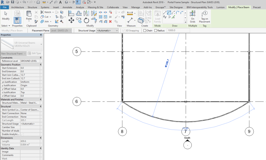
To model a curved beam, navigate to the Structure tab and select the Beam command. Then, select the Beam family from the Properties Palette. The next step is to choose the work plane. In the example, we selected the Southern most Gridline. Next, we chose a curved draw tool to make a curved beam. The curved beam will show the curvature rising up vertically from the ‚Beam/Column Joins‚ tool.
Adding a cutback
Adding a cutback to beams is a powerful tool in Revit Structure. By default, beams are joined with a structural column. However, you can change the end join type to “Start/End Extension.” Then, select the Beam/Column Joins tool to change the visible cutback of beams. This tool will not change the beam geometry or default extension settings. To add a cutback, you must be working with a plan or 3D view at a medium or high level of detail. It will display arrow controls for adjusting visible cutbacks.
Beams join each other by their endpoints. If you have several beams connected with the same endpoint, all of them will snap together when you draw another beam. Another way to connect structural beams is to use the Chain option. You can set both the endpoints of structural beams to join by their endpoints. By setting both the endpoints, you can adjust the visible cutback of the beams.
To add a cutback to beams in Revits, you must make sure that you have selected the correct type of material for the underlying structure. If you have a structural family with a steel material, you can only apply the “Cope” method, which only works on two intersecting beams. For all other elements, use the “Reference Planes and Cut Tool” method to make the cutback. This method is also effective for cutting structural elements.
Another way to add a cutback to beams in Revits is by flipping them on the model. This is a feature of the Wood Framing Truss+ add-on for Revit. This option has some quirks, however. For example, it rotates the beam by 180 degrees, but keeps some properties relative to the end. You may need to rotate the beam to achieve the desired effect.
Rotating the reference plane
If you‚re working on a project where the elevation of columns changes, you may need to change the height of beams associated with those columns. This new feature is available in Revit Structure and allows you to adjust the height of beams associated with columns. Beams must have a Start Attachment Type and End Attachment Type, and the appropriate Distance, otherwise they will not change elevation with the column.
The first step in rotating the reference plane when putting beams in your model is to select the section that you want to rotate. You can do this by selecting the Cross-Section Rotation tool and clicking the appropriate option. If you want to make the beams in a plane parallel to a section, choose Uniform/Independent. The Independent option lets you edit the beam position at two extremes, but it is only useful for sloping beams.
Once you‚ve selected the beams and framed walls, you can rotate the reference plane. You can also use the Mirror Walls and Windows in Walls feature to flip the reference line around the central axis of the wall. You can also edit the location of the reference lines for the selected Walls. These changes don‚t affect complex profile walls. The only thing you need to be aware of is that the reference lines in complex profile walls won‚t be affected.
Another useful trick in rotating the reference plane when putting beams in the Revit model is to override the graphics in the view. Overriding the projection lines of CAD drawings is helpful if you overlay them on floor plans. Otherwise, linking two different colored layers in the same file can make drafting a tedious process. This way, you can distinguish the differences between the two and save time.
About The Author

Tess Mack is a social media expert who has fallen down more times than she can count. But that hasn't stopped her from becoming one of the most well-known Twitter advocates in the world. She's also a web nerd and proud travel maven, and is considered to be one of the foremost experts on hipster-friendly social media. Tess loves sharing interesting facts with her followers, and believes that laughter is the best way to connect with people.