
Last Updated on July 27, 2023
Welcome to this article on how to access the DUT signal in a UVM component or object. If you are working with UVM and need to access the DUT signal, you have come to the right place. In this article, we will explore the importance of accessing the DUT signal in UVM and discuss various methods to achieve this. We will delve into using the UVM Register Model, the UVM Analysis Port, and the UVM TLM Interface. Additionally, we will provide you with best practices for accessing the DUT signal and troubleshoot common issues that may arise. So, let’s get started and enhance your understanding of accessing the DUT signal in UVM!
Understanding the DUT Signal
The DUT signal, also known as the Device Under Test signal, is a crucial component in UVM (Universal Verification Methodology). It represents the input or output of the component or object being tested. Understanding the DUT signal is essential for effective verification and debugging in UVM.
Here are some key points to understand about the DUT signal:
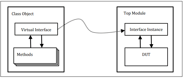
- The DUT signal is the interface between the testbench and the component or object being tested.
- It carries the data or control signals that need to be verified.
- Accessing the DUT signal allows us to monitor and manipulate the behavior of the component or object during the verification process.
- Proper understanding of the DUT signal helps in identifying and resolving issues or bugs in the design.
Overall, the DUT signal plays a vital role in the verification process and is crucial for successful verification of the component or object.
Importance of Accessing the DUT Signal in UVM
Accessing the DUT (Design Under Test) signal is a crucial aspect of working with UVM (Universal Verification Methodology). The DUT signal represents the behavior or functionality that needs to be verified in the UVM component or object. By accessing the DUT signal, we can monitor and analyze its behavior during the verification process.
Understanding the DUT signal is essential for effective verification. It allows us to ensure that the DUT is functioning correctly and meeting the desired specifications. Accessing the DUT signal provides valuable insights into the behavior of the design, helping us identify any potential issues or bugs.
Moreover, accessing the DUT signal enables us to perform various verification tasks, such as stimulus generation, checking for expected outputs, and analyzing the response of the DUT. It allows us to validate the functionality of the design and ensure its compliance with the desired requirements.
Overall, the importance of accessing the DUT signal in UVM cannot be overstated. It is a fundamental step in the verification process and plays a crucial role in ensuring the correctness and reliability of the design.
Methods to Access the DUT Signal
When working with UVM components or objects, it is often necessary to access the DUT signal. This allows us to monitor or control the behavior of the DUT (Design Under Test) during simulation. There are several methods available to access the DUT signal in UVM.
1. Using the UVM Register Model
The UVM Register Model provides a standardized way to access and manipulate registers within the DUT. By creating a register model that mirrors the DUT’s register map, we can easily read and write to specific registers and their associated fields.
2. Using the UVM Analysis Port
The UVM Analysis Port allows for the exchange of data between different components or objects in the testbench. By connecting the DUT signal to an analysis port, we can capture and analyze the signal’s behavior in real-time.
3. Using the UVM TLM Interface
The UVM TLM (Transaction Level Modeling) Interface provides a high-level abstraction for communication between different components or objects. By connecting the DUT signal to a TLM interface, we can transfer transactions or data between the DUT and other testbench components.
Overall, the choice of method to access the DUT signal depends on the specific requirements of the testbench and the desired level of abstraction. It is important to carefully consider the trade-offs and choose the method that best suits the needs of the project.
Using the UVM Register Model
The UVM Register Model is a powerful tool for accessing the DUT signal in a UVM component or object. It provides a standardized way to interact with registers and memories in the DUT, making it easier to access and manipulate the DUT signal.
- Create a register model for the DUT signal: The first step is to create a register model that represents the DUT signal. This involves defining the registers and memories that make up the DUT signal, as well as their fields and attributes.
- Connect the register model to the DUT: Once the register model is created, it needs to be connected to the DUT. This can be done using the UVM Register Layer, which provides a set of classes and methods for connecting the register model to the DUT.
- Access the DUT signal using the register model: Once the register model is connected to the DUT, you can use the methods provided by the UVM Register Layer to access and manipulate the DUT signal. This includes reading and writing to registers, as well as performing other operations on the DUT signal.
Using the UVM Register Model can greatly simplify the process of accessing the DUT signal in a UVM component or object. It provides a standardized and efficient way to interact with the DUT signal, making it easier to develop and debug UVM testbenches.
Using the UVM Analysis Port
The UVM Analysis Port is another method that can be used to access the DUT signal in a UVM component or object. This method involves creating an analysis port in the component or object and connecting it to an analysis export in the testbench. Here are the steps to use the UVM Analysis Port:
- Create an analysis port in the UVM component or object.
- Define the analysis export in the testbench.
- Connect the analysis port to the analysis export using the connect method.
- Implement the write method in the UVM component or object to send data through the analysis port.
- Implement the write method in the testbench to receive the data from the analysis port.
The UVM Analysis Port provides a flexible and efficient way to pass data between the DUT and the testbench. It allows for asynchronous communication and can handle large amounts of data. However, it requires careful synchronization and coordination between the component or object and the testbench to ensure proper data transfer.
Using the UVM TLM Interface
The UVM TLM (Transaction Level Modeling) interface is another method to access the DUT (Design Under Test) signal in a UVM (Universal Verification Methodology) component or object. This interface allows for communication between different components or objects at the transaction level, enabling efficient and flexible data transfer.
By using the UVM TLM interface, the DUT signal can be accessed and monitored in a non-intrusive manner. This means that the functionality of the DUT is not affected by the monitoring process, ensuring accurate and reliable results.
The UVM TLM interface provides a standardized way to exchange data between components or objects, making it easier to integrate different parts of the verification environment. It allows for the creation of reusable and modular verification components, improving productivity and reducing development time.
When using the UVM TLM interface to access the DUT signal, it is important to follow best practices to ensure proper functionality and avoid common issues. These best practices include proper configuration and initialization of the interface, handling of transactions, and synchronization between components or objects.
Best Practices for Accessing the DUT Signal
When it comes to accessing the DUT signal in a UVM component or object, there are several best practices that can help ensure smooth and efficient operation. These practices have been developed through years of experience and can greatly improve the overall performance of your UVM environment.
1. Use Appropriate Interfaces
One of the key best practices is to use the appropriate interfaces for accessing the DUT signal. Depending on the specific requirements of your design, you may choose to use the UVM Register Model, the UVM Analysis Port, or the UVM TLM Interface. Each of these interfaces has its own advantages and disadvantages, so it is important to carefully consider which one is best suited for your needs.
2. Follow Naming Conventions
Another important best practice is to follow naming conventions when accessing the DUT signal. This can help improve code readability and maintainability, making it easier for other team members to understand and work with your code. It is also recommended to use meaningful and descriptive names for your signals, variables, and methods.
3. Implement Appropriate Error Handling
Implementing appropriate error handling mechanisms is crucial when accessing the DUT signal. This can help detect and handle any unexpected issues or errors that may occur during the operation. It is recommended to use assertions, error codes, or exception handling techniques to ensure that any errors are properly handled and reported.
4. Perform Thorough Testing
Thorough testing is essential when accessing the DUT signal. This includes both unit testing and integration testing to ensure that the signal is being accessed correctly and that it is functioning as expected. It is also important to test for any potential edge cases or corner cases that may arise during the operation.
By following these best practices, you can ensure that the DUT signal is accessed efficiently and effectively in your UVM component or object. This will help improve the overall performance and reliability of your UVM environment, leading to a more successful and robust design.
Troubleshooting Common Issues
While accessing the DUT signal in a UVM component or object can be a powerful tool, it is not without its challenges. In this section, we will discuss some common issues that may arise and provide troubleshooting tips to help you overcome them.
1. Signal not found
One common issue is when the DUT signal cannot be found. This can happen if the signal name is misspelled or if the signal is not properly connected in the testbench. To troubleshoot this issue, double-check the signal name and ensure that it is correctly connected in the testbench hierarchy.
2. Incorrect signal value
Another issue that may occur is when the DUT signal does not have the expected value. This can happen if there is a bug in the design or if the signal is not being properly sampled in the testbench. To troubleshoot this issue, review the design code and verify that the signal is being correctly sampled in the testbench.
By being aware of these common issues and following the troubleshooting tips provided, you can ensure a smooth and successful access to the DUT signal in your UVM component or object.
Wrapping Up
In conclusion, accessing the DUT signal in a UVM component or object is crucial for effective verification and debugging of a design. Throughout this article, we have discussed the various methods available to access the DUT signal, including the UVM Register Model, UVM Analysis Port, and UVM TLM Interface.
By utilizing these methods, engineers can gain valuable insights into the behavior of the DUT and ensure its proper functionality. It is important to follow best practices when accessing the DUT signal, such as using appropriate synchronization mechanisms and avoiding race conditions.
However, it is not uncommon to encounter issues when accessing the DUT signal, such as incorrect signal values or missing data. Troubleshooting these issues requires a systematic approach, including checking for proper configuration, verifying the correctness of the testbench, and analyzing the simulation results.
Overall, accessing the DUT signal in a UVM environment is a critical aspect of the verification process, and engineers must be well-versed in the available methods and best practices to ensure accurate and reliable results. By following the guidelines outlined in this article, engineers can effectively access the DUT signal and enhance the overall quality of their verification process.
Learn how to access the DUT signal in a UVM component/object with these effective methods and best practices.
About The Author

Mindy Vu is a part time shoe model and professional mum. She loves to cook and has been proclaimed the best cook in the world by her friends and family. She adores her pet dog Twinkie, and is happily married to her books.