
Last Updated on July 23, 2023
Short Answer
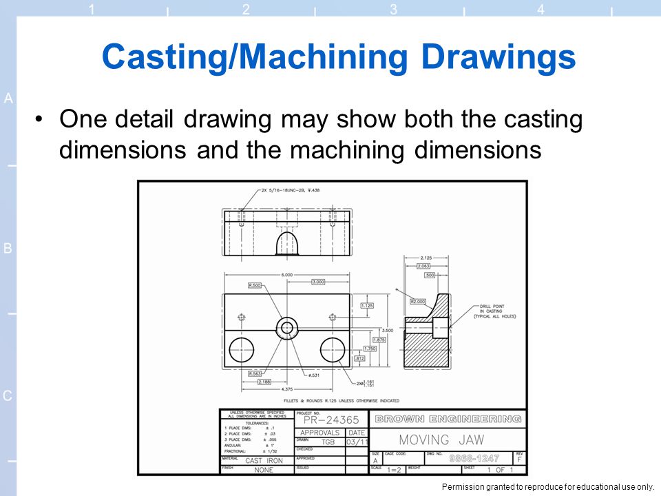
To dimension a casting drawing, one must carefully indicate the measurements and specifications of the casting in a clear and concise manner. This involves using various symbols, lines, and notations to represent the dimensions, tolerances, and surface finishes of the casting. Additionally, it is important to consider the functional requirements and manufacturing constraints while dimensioning the drawing. By following industry standards and guidelines, such as ASME Y14.5, one can ensure that the casting drawing provides all the necessary information for the successful production of the casting.
Accurate dimensioning is crucial when it comes to casting drawings. In order to ensure precise and reliable results, it is important to understand the importance of dimensioning and how to do it correctly. This article will cover the basics of dimensioning a casting drawing, as well as key considerations for dimensioning complex casting features. It will also provide best practices for dimensioning critical dimensions, techniques for ensuring proper fit and alignment, and guidelines for specifying surface finishes. Additionally, it will discuss the role of tolerances in dimensioning and provide tips for communicating material requirements. By mastering dimensioning techniques, you can create casting drawings that are precise and reliable.
The basics of dimensioning a casting drawing
1. Use clear and concise dimensioning techniques
Use standard dimensioning symbols and conventions to ensure clarity and consistency.
– Avoid overcrowding the drawing with dimensions, but provide enough information for the foundry to understand the requirements.
2. Consider the casting process
– Understand the limitations and capabilities of the casting process being used.
– Take into account factors such as shrinkage, draft angles, and machining allowances when dimensioning the drawing.
3. Specify critical dimensions
– Identify the dimensions that are critical to the functionality and fit of the casting.
– Provide clear and precise tolerances for these dimensions to ensure proper fit and alignment.
4. Communicate material requirements
– Specify the type of material to be used for the casting.
– Indicate any special requirements such as heat treatment or surface finishes.
– By following these basic dimensioning practices, you can create casting drawings that are accurate, precise, and easy to understand.
Key considerations for dimensioning complex casting features
When dimensioning complex casting features, there are several key considerations that must be taken into account to ensure accuracy and reliability. One important consideration is the selection of the appropriate reference points for dimensioning. These reference points should be easily identifiable and should provide a clear and unambiguous starting point for the dimensioning process.
Another important consideration is the use of proper dimensioning techniques to accurately represent the shape and size of the casting feature. This may involve the use of multiple dimensions, such as length, width, and height, to fully describe the feature. It is also important to consider the tolerances that are required for the casting feature, as these will impact the final dimensions of the part.
Additionally, when dimensioning complex casting features, it is important to consider any interference or clearance requirements that may be necessary for the part to function properly. This may involve dimensioning features such as holes or slots to ensure proper fit and alignment with other components.
Overall, dimensioning complex casting features requires careful consideration of reference points, dimensioning techniques, tolerances, and interference or clearance requirements. By following these key considerations, accurate and reliable casting drawings can be produced.
Best practices for dimensioning critical dimensions in casting drawings
When dimensioning critical dimensions in casting drawings, it is crucial to follow certain best practices to ensure accuracy and reliability. Here are some key guidelines to consider:
1. Use clear and concise dimensioning
It is important to use clear and concise dimensioning to avoid any confusion or misinterpretation. Use appropriate dimensioning symbols and avoid overcrowding the drawing with unnecessary dimensions.
2. Prioritize critical dimensions
Identify the critical dimensions in the casting drawing and prioritize them. These are the dimensions that have a significant impact on the functionality and performance of the casting. Ensure that these dimensions are clearly highlighted and given more emphasis.
3. Provide reference dimensions
Include reference dimensions that can be used to verify the accuracy of other dimensions. These reference dimensions should be easily measurable and should not be affected by any manufacturing processes.
4. Consider manufacturing capabilities
Take into account the capabilities of the manufacturing process when dimensioning critical dimensions. Ensure that the dimensions are within the achievable tolerances of the casting process to avoid any issues during production.
By following these best practices, you can ensure that the critical dimensions in your casting drawings are accurately dimensioned, leading to precise and reliable casting designs.
Dimensioning techniques for ensuring proper fit and alignment in casting designs
When dimensioning a casting drawing, it is crucial to ensure that the dimensions provided result in a proper fit and alignment of the casting components. Here are some techniques to achieve this:
- Use reference dimensions: Reference dimensions are used to establish the relationship between different features of the casting. By providing reference dimensions, you can ensure that the components fit together correctly.
- Consider functional requirements: Before dimensioning a casting drawing, it is important to understand the functional requirements of the casting. This includes factors such as clearance, interference, and alignment. By considering these requirements, you can dimension the drawing accordingly.
- Use geometric dimensioning and tolerancing (GD&T): GD&T is a system for defining and communicating engineering tolerances. By using GD&T symbols and annotations, you can specify the allowable variations in size, form, and orientation of the casting components.
- Consider assembly processes: When dimensioning a casting drawing, it is important to consider the assembly processes that will be used. This includes factors such as shrinkage, machining allowances, and assembly clearances. By considering these factors, you can ensure that the casting components fit together properly during assembly.
- Consult with manufacturing experts: If you are unsure about the dimensioning techniques for ensuring proper fit and alignment in casting designs, it is always a good idea to consult with manufacturing experts. They can provide valuable insights and guidance based on their experience and expertise.
The role of tolerances in dimensioning casting drawings
When dimensioning casting drawings, it is crucial to include tolerances. Tolerances define the acceptable range of variation for each dimension, ensuring that the final casting meets the required specifications. Here are some key points to consider when incorporating tolerances in casting drawings:
- Understand the application: Before determining tolerances, it is important to understand the function and purpose of the casting. This will help in setting appropriate tolerances that align with the intended use of the casting.
- Consider manufacturing capabilities: Tolerances should take into account the capabilities of the manufacturing process. It is essential to work closely with the foundry or manufacturer to determine achievable tolerances based on their equipment and expertise.
- Balance cost and precision: Tighter tolerances may result in higher manufacturing costs. It is important to strike a balance between the desired precision and the cost implications. Consult with the manufacturer to find the optimal tolerance range that meets both functional requirements and cost considerations.
- Specify tolerances clearly: Tolerances should be clearly indicated on the casting drawing using standard symbols and notations. This ensures that there is no ambiguity or confusion during the manufacturing process.
- Consider assembly requirements: If the casting is part of an assembly, it is important to consider the tolerances of other components to ensure proper fit and functionality. Coordinate with the design team to ensure compatibility between the casting and other parts.
By incorporating appropriate tolerances in casting drawings, designers can ensure that the final casting meets the required specifications and functions as intended.
Dimensioning guidelines for specifying surface finishes in casting drawings
When dimensioning a casting drawing, it is crucial to include specifications for surface finishes. Surface finishes play a significant role in the functionality and aesthetics of the final casting. Here are some guidelines to follow when specifying surface finishes:
1. Understand the purpose
Before specifying a surface finish, it is important to understand the purpose it serves. Surface finishes can enhance the appearance, improve corrosion resistance, or provide better lubrication.
2. Use appropriate symbols
When dimensioning a casting drawing, use the appropriate symbols to indicate the desired surface finish. Common symbols include roughness average (Ra), surface roughness (Rz), and surface texture.
Consider the casting material
The choice of surface finish should be based on the casting material. Different materials may require specific finishes to achieve the desired results.
4. Consult industry standards
Refer to industry standards and specifications to ensure that the specified surface finish meets the required criteria. This will help ensure consistency and compatibility with manufacturing processes.
By following these dimensioning guidelines for specifying surface finishes, you can ensure that your casting drawings accurately communicate the desired surface quality and meet the requirements of the final product.
Dimensioning Tips for Communicating Material Requirements in Casting Designs
When dimensioning a casting drawing, it is crucial to accurately communicate the material requirements to ensure the desired outcome of the casting design. Here are some tips to help you effectively convey the material specifications:
1. Specify the material type
Clearly state the type of material that should be used for the casting. This can include the specific alloy or grade of metal, as well as any additional requirements such as heat treatment or surface coatings.
2. Provide dimensional tolerances
Dimensional tolerances play a vital role in determining the accuracy and quality of the casting. Clearly define the acceptable range of dimensions for each feature, taking into account factors such as shrinkage and machining allowances.
Indicate material properties
If certain material properties are critical for the casting’s performance, such as strength or corrosion resistance, make sure to specify them. This will help ensure that the casting is made from a material that meets the necessary requirements.
4. Consider environmental factors
If the casting will be exposed to specific environmental conditions, such as high temperatures or corrosive substances, it is important to communicate these requirements. This will help the manufacturer select a material that can withstand the intended operating conditions.
By following these dimensioning tips, you can effectively communicate the material requirements in your casting designs, resulting in precise and reliable outcomes.
Conclusion: Mastering Dimensioning Techniques for Precise and Reliable Casting Drawings
In conclusion, accurate dimensioning is crucial in creating precise and reliable casting drawings. It ensures that the final product meets the required specifications and functions as intended. By following the basics of dimensioning, considering key factors for complex features, and implementing best practices for critical dimensions, designers can achieve optimal results.
Proper fit and alignment are essential in casting designs, and dimensioning techniques play a significant role in achieving this. By using appropriate tolerances, designers can ensure that the parts fit together seamlessly and function properly. Additionally, specifying surface finishes accurately is important for achieving the desired appearance and functionality of the casting.
Communicating material requirements effectively is another crucial aspect of dimensioning in casting designs. By clearly indicating the type of material and any specific requirements, designers can ensure that the casting is made from the appropriate material and meets the necessary standards.
In conclusion, mastering dimensioning techniques is essential for creating precise and reliable casting drawings. By following the guidelines and best practices outlined in this article, designers can ensure that their casting designs are accurate, functional, and meet the required specifications.
Frequently Asked Questions
What is the importance of accurate dimensioning in casting drawings?
Accurate dimensioning in casting drawings is crucial as it ensures that the final casting product meets the required specifications and fits properly within the overall design. It helps to avoid any potential issues or errors during the casting process and ensures the reliability and functionality of the finished product.
What are the basics of dimensioning a casting drawing?
The basics of dimensioning a casting drawing involve clearly indicating the size, shape, and location of various features of the casting. This includes providing measurements for length, width, height, and any other relevant dimensions. It is important to use standard dimensioning practices and symbols to ensure clear communication between the designer and the manufacturer.
What are the key considerations for dimensioning complex casting features?
When dimensioning complex casting features, it is important to consider factors such as the casting process, material shrinkage, and machining allowances. These considerations help to ensure that the final casting will have the desired dimensions and tolerances after the casting process and any subsequent machining operations.
What are the best practices for dimensioning critical dimensions in casting drawings?
When dimensioning critical dimensions in casting drawings, it is recommended to use direct dimensions rather than indirect dimensions. Direct dimensions provide specific measurements for critical features, while indirect dimensions rely on reference dimensions or calculations. Additionally, it is important to clearly specify any required tolerances for critical dimensions to ensure the desired level of precision.
What dimensioning techniques can be used to ensure proper fit and alignment in casting designs?
To ensure proper fit and alignment in casting designs, dimensioning techniques such as bilateral tolerancing, geometric dimensioning and tolerancing (GD&T), and datum references can be used. These techniques help to define the allowable variations in size, shape, and orientation of the casting features, ensuring that the final product will fit and function as intended.
About The Author

Alison Sowle is the typical tv guru. With a social media evangelist background, she knows how to get her message out there. However, she's also an introvert at heart and loves nothing more than writing for hours on end. She's a passionate creator who takes great joy in learning about new cultures - especially when it comes to beer!