
Last Updated on September 17, 2022
The first step in learning how to join two alignments in Civil 3D is to create one. After that, you should create the other. For more information on this topic, read the sections below. This article covers creating a vertical alignment, tangent, and floating entity, as well as deleting a point of intersection. In addition, we’ll cover how to join two alignments with other elements in the same project.
Create a vertical alignment
If you want to create a vertical alignment for a road, there are a few steps you should follow to get it right the first time. In civil 3d, the alignment will be set using the speed of the roadway and the sight distance for the drivers. The last step in creating a vertical alignment is determining the minimum slope of the road. If the slope is too low, the roadway may pond, and a slope higher than 1.0% will not provide adequate drainage. The proper jurisdiction will have its own requirements, so be sure to check with them.
After you’ve defined the Start Station, you’ll need to select the other tools to create the alignment. First, open the Start Station tool. It should be located at the IP of the curves. Select the option to include the Starting Station in the drawing. Next, click on the Start Station Manipulator. This will present you with the magnitude and value of the Start Station. After you’ve set the starting location, click OK.
Next, select the Feature Definition option in the Road Design menu. Select the option for Alignment by Elements or Complex By PI. You can also use the Horizontal Geometry Task to create all the alignments. To create all the alignments in a road, you can also use the OpenRoads Help in the Civil Tools menu. If you have any questions, don’t hesitate to ask.
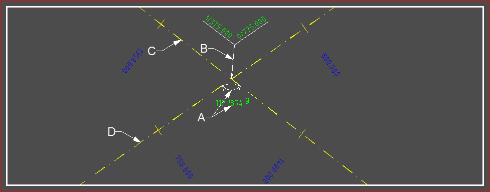
Create a tangent
To create a tangent between two alignments, open the Alignment by Layout toolbar in Civil 3D. There, you can choose to either create a free curve or use the default radii. In the latter case, you can also edit the points-of-intersection. In the former case, the tangent is automatically added. If the tangent does not follow a geometric rule, you can modify it later.
A free curve is drawn between a line or spiral, and is updated to maintain tangency. In addition, free spirals can be included in the layout as single spiral elements, pair of compound spirals, reverse spirals, 3-element spiral-curve-spiral combinations, or even a combination of the three. Civil 3D 2007 offers free compound spirals. You can draw multiple spirals by using the same tool.
To create a tangent between two alignments, first select the alignment that has the shortest distance between the two points. For example, if a line connects two points, then it will be tangent to both points. The tangent must not cross both alignments and should be a single line with an angle less than 180 degrees. To create a tangent between two alignments in Civil 3D, you can use the alignment layout tools.
Create a floating entity
In order to create a floating entity to join two alignments, you must use the Layout tool. This tool will allow you to create a new alignment using a centerline. This tool will also allow you to modify the alignment that is already created. Using the layout tool, you can create a new alignment by specifying design conditions. You can also use the tool to draw the centerline.
To create a floating entity, select the curve entities you want to join. You can then set the length of the curve to a specified value. Then, choose a point to join to. The point must be mathematically possible, but you can move the curve entity along the axis using the tool. A floating entity will maintain tangency between the two alignments. This feature will make it easier to join the two alignments.
In addition to the new features, this update also contains fixes for previous versions of Autodesk Civil 3D. It addresses several stability problems, including a bug in which an intersection became out-of-date after saving a drawing. This problem is also fixed in another way: the issue that caused intersections and corridors to become out-of-date when you use UNDO and PURGE to remove parcel segments from your drawing.
Deleting a point of intersection
In Civil 3D, you can delete a point of intersection (PI) from a feature line, survey figure, or 2D polyline. In the Surface Definition, click the Edit button and choose the option to Delete a point of intersection. Once the point of intersection has been deleted, it can no longer be seen. In some cases, you may want to move the PI to another location.
Delete an intersection object from the drawing. This will remove the intersection object from the drawing, but it won’t remove the adjacent corridor objects. If the intersection object is inside of another object, you need to delete the existing corridor. You can also delete an intersection object by selecting it and then clicking the Remove button. Then, select a corridor object that lies inside of the intersection area and click the Delete button.
In Civil 3D, you can also use a point of intersection to create a curved surface. You can even connect it to another point using the PtConnect command. In Sincpac C3D, this command is especially helpful for connecting Cogo Points. This software does not offer field-to-finish solutions, such as traverse adjustment software and file format converters. However, it does have some useful features for all users.
Copying and pasting targets between subassemblies
To simplify the application of targets, the new version of Civil 3D enables copying and pasting targets between subassessments. To do so, right-click on the target and choose the context menu. This window includes commands to copy, paste, zoom, pan, and match parameters in different subassemblies. Here are a few examples.
The first step is to create the assembly. This is usually the same as copying and pasting targets between subassemblies. Then, paste the new assembly into the original subassembly. If you have an assembly that has been successfully used before, copy and paste it into the new one. You can also set reference parameters for a subassembly on the Construction tab.
This step is not easy to complete. There are many factors to consider before copying and pasting targets between subassemblies. First, make sure to check the point numbers of the subsequent elements. Then, check the input/output parameters of the targets. This step can take a long time if you are working on a complex model with lots of subassemblies.
Secondly, be sure to check if the style supports offsets. You can do this with the Civil 3D API. For example, if you need to change slope to match the curve, you can add the offsets in the 2018 folder. Lastly, make sure to check the alignments of the intersections with the intersections and the adjacent streets. Once you’ve done this, you can easily adjust the locations of the crossovers and paste them in the desired subassemblies.
Creating a corridor
In Civil 3D, a corridor is defined by its alignment, profile, and assembly. The user can then create additional components for a corridor, such as slopes, surfaces, and frequencies, and copy them to other corridors. Once a corridor is defined, it is easy to use it to create the rest of the corridor. The Civil 3D 2022.1 update provides a new feature called “Corridor Templates” that make creating corridors a breeze.
The assembly that creates a corridor consists of a series of subassemblies, such as road lanes, curb and gutter, shoulder, sidewalks, and tie in grades. When creating a corridor, be sure to select a clean tie between the existing grade and the finished grade. Be sure to note that voids and irregularities will result if the composite surface is not glued together correctly. Another method is to use a single polyline to enclose the entire corridor design, looping around void areas, and wrapping around the perimeter.
The first step in creating a corridor is to create the baselines and 2D sections that are the basic building blocks of the roadway. From there, you can create a corridor that spans multiple baselines and surface models. In this way, you can design a road with multiple alignments and intersections. You can also edit the assembly frequency in corridors that have intersection objects. The Corridor ribbon will provide you with convenient access to a number of editing commands.
About The Author

Mindy Vu is a part time shoe model and professional mum. She loves to cook and has been proclaimed the best cook in the world by her friends and family. She adores her pet dog Twinkie, and is happily married to her books.